
Industry knowledge
You are here: Home > Industry knowledgeContentCar debris box shell mold design analysis (mold industry) enhanced level PA66 + GF30%
In this article, to analyze the product is a car's debris box shell, the material is enhanced PA66 + GF30%, this product is very complex internal structure, shape is also more complex. (138mm) the total thickness of the mold is very large, use a relatively large injection molding machine to produce (Haitian 350 ), the overall size of the mold is large, ). If the weight of the product, 200 tons of injection molding machine can be formed, and how to ensure the normal production of products in the case of a substantial reduction in mold thickness, is the designer of this set of challenges.
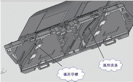
figure 1
This product is a flagship product of a factory, has been produced for some time, because the original mold structure is not very reasonable, take the product is very difficult. Class production is very low, the defect rate is also high, mainly due to the original mold structure can not be arranged twice the top out, so take the product is difficult to operate the workers shaking left and right products can be removed, it is easy to products The lower part of the exposed part of the plastic wounds. Followed by a large die thickness (700mm), to use a large injection molding machine to produce, costly. To this end, we have redesigned the mold.
Gate design
Because the raw material is added 30% glass fiber, the liquidity is very poor, the original mold is the use of four hot runner into the glue, into the point of the diameter of Φ3mm, encountered this situation is not serious, because The surface of the glue is assembled inside the car dashboard, and does not affect any appearance. In fact, the mold is always thick thick thick one of the main reasons is the use of hot runner system. Mold thickness can not be lowered. After consideration, we used such a gate, and the old mold into the plastic exactly the same, or 4:00 into the glue, into the glue position and the original mold the same. But it is a large outlet structure (see Figure 2).
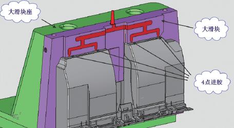
figure 2
Figure 3 below shows the mold flow analysis provided by Moldex 3D.
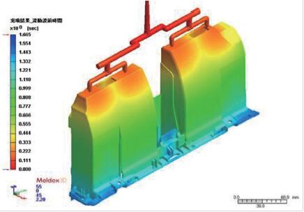
image 3
The final use of large sliders and fixed-mode joint surface to do cross-flow channel, in order to make the point into the product of the middle of the point, we are in the large slider and the fixed mold on the surface of the arrangement of the two boss (See Figure 4), the removal of the hot runner, into such a gate, the total height of the mold reduced by 120mm, injection molding machine from the original 350 tons to 220 tons. Mold manufacturing costs are also reduced by 40,000 yuan (hot runner cost hot runner board costs). Cleverly in the big slider on the two, will be moved into the middle of the product point, greatly reducing the difficulty of mold manufacturing.
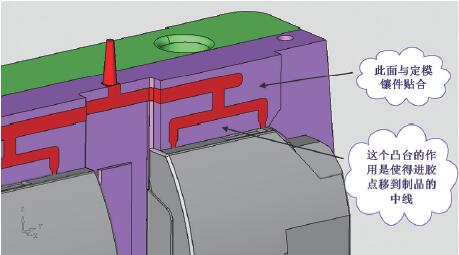
Figure 4
Design and composition of large sliders
The large slider is made up of the slider body and the slider block. The slider body is made of NAK80. The slider block is made of CrWuMn, which reduces the production cost of the mold. Processing is also more convenient, we look at the back of the slider body, I have a good layout here, see Figure 5.
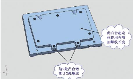
Figure 5
As can be seen from Figure 5, in the slider body on the back of the rectangular side of the increase in the two boss, why?
Because in order to extend the life of the mold, the slider body with a more expensive steel, and the heat treatment, in order to save the cost of the mold, slider body to do relatively thin, the thickest place is 43.6mm, remove the 15mm positioning steps, Leaving 28.6mm. It is difficult to arrange the screws connected to the large slider blocks, and the bottom of the thread can not be drilled so much that the actual effective number of teeth is not ideal. Because the entire large slider system cooling water ring of the ring is to rely on the seven M12 hexagon thread to compress, if the effective number of screws is not enough screws, the screws can not be too tight, otherwise it will slip teeth. Now increase the two small square, the actual length of the thread increased by 15mm, there is no worries. From the manufacturing cost of the mold, now the big slider to increase the reliability, but did not increase the material and manufacturing costs. This is a very small detail of the mold design, but the accumulation of these details, so that we in the design process, and gradually improve the design level of mold designers.
Design of Cooling System for Large Slider
As can be seen from Fig. 6, the slider body and the slider block are connected by seven M12 hexagon screws, and the seal is arranged at the position where the two are connected to the water.
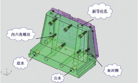
Figure 6
PA66 melt temperature is very high, and the product shape is complex, requiring more stable assembly size. Therefore, the position of the cooling water hole of the large slider system is more important, the actual production is used for the mold temperature, the temperature constant at 110 ° C. Now I will be on the slider body on the body, through the seal ring from the slider block, arranged on both sides of the mold. This processing is more convenient.
The power of the large slider is pulled by the force of the injection molding machine, and the large slider is pulled out by the oblique guide post on the setting frame. The diagonal guide of the large slider is through the mold. The combination of the big slider and the large mold inserts forms the gate, and the injection nozzle of the injection molding machine is directly on the fixed mold. This can greatly shorten the main channel, reducing the injection of injection pressure. The mold itself by the alternating stress drop, so that the life of the mold is also greatly extended.
The design of the mold
Fixed mold is designed as a whole, there is no inserts, see Figure 7.
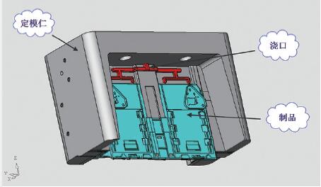
Figure 7
The inner surface of the mold is fitted with the large slider body, forming a cross flow path on the fitting surface, and then divided into a 4-point flow path (see Fig. 8). The design of the mold is very routine, but in order to reduce the stress after the product is molded, the design of the cooling system is critical.
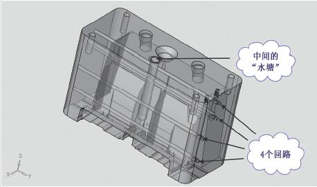
Figure 8
As can be seen from Figure 8, the fixed-hole in addition to the arrangement of the horizontal four waterways, the middle of the protruding part of the arrangement of a "pond", so that the entire moving mold of the waterway is more uniform, more balanced heat exchange , The residual stress in the product to a minimum.
In the design of the small slider, the other side of the product is more complex, we use a whole slider (see Figure 9). The small slider consists of a slider body and a small slider block, fixed with screws, and pressed the seal ring to form a combined waterway. The small slider is also tilted by the diagonal guide column, and the big slider is different, the diagonal column is fixed in a dedicated oblique guide column seat. See figure.
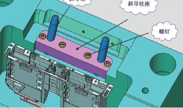
Figure 9
This design and processing are relatively simple. The limit of the small slider is achieved by means of two limit blocks, see the opposite side of the small slider block (see Figure 10).
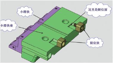
Figure 10
Design of Core - pulling Mechanism in Dynamic Mold
The appearance of the dynamic mold is the most exciting part of the mold, there is considerable difficulty, we first look at the appearance of the entire dynamic mode (see Figure 11).
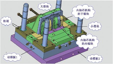
Figure 11
(See Figure 12), the inner core is divided into two parts, the middle part is fixed on the moving template 2, and with the movement of the template 2 together. The second side is arranged on the movable die plate 1. The slanting "T" type on the side of the lower block slides inward when it moves downward. In order to ensure that the movement of the inner block is reliable and has a long life, we have designed a series of corresponding friction mechanism and fixing mechanism, which will be described in detail.
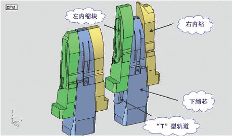
Figure 12
1. Template 1 (active template) layout. In fact, the active moving die plate 1 is a special push plate mechanism, all kinds of parts are attached to the push plate (moving template 1), only the lower core is fixed on the moving template 2. The push plate (movable plate 1) is pushed out by the top of the plunger of the injection molding machine (see Fig. 13). As the inner block has a slant "T" type block, so when the inner core shrink down, the internal slider has a move inward.
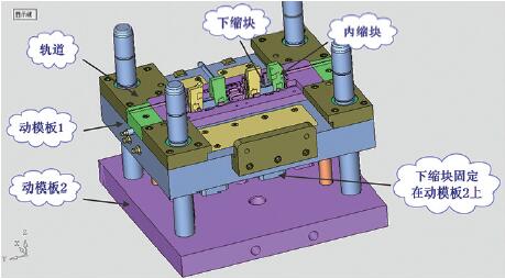
Figure 13
2. Design of internal sliders. As the inside of the slider in the slide only need to slide 3mm, shrink the core only need to shrink 35mm is enough, but because the product is relatively deep, in fact, moving the template 1 to push the product out of 138m. This is a contradiction between the inner slide, because the inner slide if the forward 138mm, two within the slider on the "fight" the. How to make the inner slider only inward shift 3mm, but also forward 138mm. The solution to this problem can be seen in Figure 14.
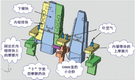
Figure 14
For the sake of insurance, we set the inner slider to move inward by 4mm. The bottom of the inner slide is fixed with a friction plate. When the mold is locked, a "10" Wide small steps, to withstand the bottom of the slider connected to the bottom of the friction plate, making the plastic shrink when the slider is not back. As can be seen from Fig. 14, the upper part of the "foot" of the inner slide has a part called "upper friction plate" which ensures that the inner slide moves smoothly inward and, at the same time, Block the precise positioning, while the "friction plate" there is a role, we see in Figure 14 a part called "needle cylinder" is used for secondary stripping, followed by a detailed introduction, This "upper friction plate" is a "needle type cylinder" fixing block and a compressed air passage.
In the lower part of the block and the relative movement of the slider, due to the small step of 4mm wide block, within the slider can not be down, only to slide inward, when the next block finished 45.72mm, the inside of the slider just go Finished 4mm.
When the inner slider is slid 4mm inward, when the step is over the small step, the friction block at the bottom of the inner slider stops sliding inwardly, and moves downwards with the inner block.
When the mold, the shrinkage of the forward movement, due to friction, within the slider in the forward movement at the same time will move outwards, when the protection of the role of "ten" type of friction block will block the shrink The slider, so that it can only be up, can not be out. When the lower shrinkage block continues to move upwards to the foot of the original inner block, when the foot of the inner block is moved away from the 4 mm step on the "ten" type friction block, the lower shrinkage block continues upward due to the block of the upper friction plate. Mandatory outward movement 4mm, until the final position.
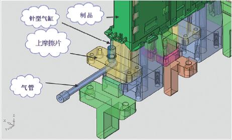
Figure 15
This is a very clever design, inspired by the cross from the church. When the internal shrinkage with the downward movement, the final position of the positioning is by this small plate, called the friction plate, but also needle cylinder fixed plate, this small plate has two functions: First, The final positioning, the second is arranged a group of needle cylinder, the product of the second top out. As the set of molds without thimble and pad feet, the product of the second out of the very difficult, the needle cylinder is a good thing, it can be in any part of the mold, any angle out.
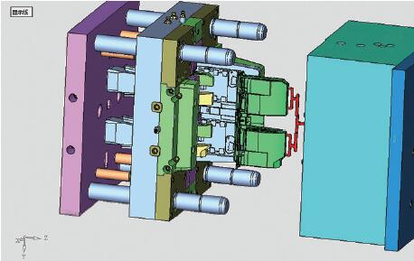
Figure 16
This is the case in the mold (see Figure 15), so that the product can be manually clamped and fully automated (see Figure 16).
Concluding remarks
This mold has several bright spots: the first is the original is a very headache mold, can now be fully automated production, and the use of injection molding machine smaller one, saving energy; the second is to cancel the hot runner, Large outlet, saving the mold manufacturing costs, the highlight is in the large slider and fixed mold inserts on the plane of the combination of two bosses, into the plastic point into the middle of the product; the third is the use of the cross Protect the friction block, so that the action of the internal slider is safe and reliable.

Previous: No Information
下一条: I am a polycarbonate, everyone calls me PC, here's my resume and fill plastic flame retardant
Related Industry Knowledge
- Hello, I am a PET, here's my resume! (Collection) manufacturer; manufacturers supply specializing in the modification, processing the custom; modified engineering plastics plastics
- I am the ABS, the scientific name: acrylonitrile-butadiene-styrene, here's my resume! Supply of modified plastics modified engineering plastics
- PA/ABS introduction to marriage--enhanced levels; filled plastic; flame retardant; modified processing injection materials nylon PA66; modified nylon and polyamide nylon; modified polyamide engineering plastics
- I am pp, PP called me, here's my resume! Pp; polypropylene fiber modification of polypropylene staple fibre manufacturer plastic
- I'm PE, PE called me, here's my resume! Reinforced grade/flame retardant modified engineering plastics manufacturers
- I am a Pom, POM called me, here's my resume (collection) engineering plastics modification of plastics
- I am a polycarbonate, everyone calls me PC, here's my resume and fill plastic flame retardant